It reveals the parts of the circuit as streamlined forms and also the power and signal links between the gadgets.
Nmea 2000 power cable wiring diagram.
A nmea 2000 power cable terminators an additional drop backbone cable and additional t connectors are not included with a gfs 10 fuel sensor.
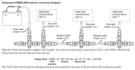
The nmea 2000 cable system uses a trunk sometimes referred to as the backbone and drop line topology as shown in figure 1.
Use a nmea 2000 power cable to connect your nmea 2000 backbone to the auxiliary power switch on your boat.
Seatalk ng 5 way connector.
If you require a longer cable run use a t junction in the middle of the run to tie in 12 volt dc power.
The maximum length for a single drop cable is 20 feet.
A wiring diagram is a simplified conventional pictorial depiction of an electrical circuit.
Starter kit part number.
Nmea 2000 signals can be hampered by resistance which increases with cable length so keep the length for a single drop cable to less than 20 feet.
The following catalog pages contain the nmea 2000 approved network interconnect.
Maretron nmea 2000 cables connectors about nmea 2000 cables and connectors the nmea 2000 standard goes beyond defining message content and includes requirements for the cabling used to interconnect electronic components referred to as the physical interface.
If you require a longer cable run to connect an item such as a transducer or sea surface temperature sensor use a t junction to either at the end or the middle of the run to tie in 12 volt power.
The seatalk ng starter kit is the perfect way to get started with your seatalk ng compatible raymarine product.
In this example a t connector is included with a garmin gfs 10 fuel sensor.
If you do not have an auxiliary power switch or if connecting to the auxiliary power switch causes electrical interference connect the nmea 2000 power cable directly to the battery and install an in line switch.
Collection of nmea 2000 wiring diagram.
The seatalk ng starter kit.
A wiring diagram is a simplified conventional photographic depiction of an electric circuit.
Assortment of nmea wiring diagram.
In the sample box diagram a complete nmea 2000 network is shown and the parts included with the sensor are shaded.
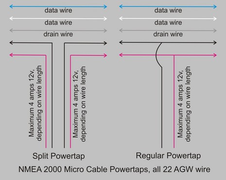
The nmea 2000 cable system includes five wires within a single waterproof cable.
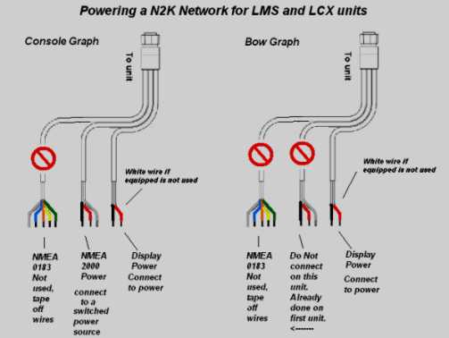
In this case you would power your nmea network by connecting one of your lms or lcx unit power cables marked nmea power to a switched power source.
The drain wire shields the signal power.
What s in the kit.
Seatalk ng backbone terminator x2.
Nmea networking universalyachtparts 2000 adrena software power problem part 2 panbo missing the obvious cm 0729 0183 to db9 wiring diagram proper installation ibex 2018 session 813 vo 0723 t connector building an network salt water sportsman nmea networking universalyachtparts nmea 2000 adrena software nmea 2000 power problem part 2 panbo nmea 2000 missing the obvious cm 0729 read more.
The 5 way connector forms the start of your seatalk ng backbone and your seatalk ng product is connected via a spur cable.